With the IoT and big data driving the need for increased bandwidth and processing speeds to access, transmit and store more data than ever before, the proliferation of high-speed fiber connections in the LAN and data center continues to grow. An average data center today can contain thousands of fiber links with high-speed computing environments reaching into the hundreds of thousands.
Ethernet application standards have fortunately been keeping pace with 40 and 100 gigabit speeds well established and 400 GbE already under development. But as transmission speeds have increased, fiber insertion loss (e.g., attenuation) requirements have become more stringent than ever. Insertion loss budgets are now one of the top concerns among network and data center managers; staying within the insertion loss budget for a specific application ensures that transmitted signals properly reach their final destination.
Optical loss test sets (OLTS) can help network and data center mangers ensure that fiber links stay within the loss budget and provide the intended performance
Here are best practices to OLTS testing that are essential to acquiring the most accurate loss measurements. With loss budgets for 40 and 100 gig applications about half of what they were for 10 gig, every 0.1dB of loss matters.
Reference cords
An OLTS uses a stable light source on one end and a power meter on the other for measuring link loss. Reference cords are required to connect to the cable under test--what’s called a “launch” reference cord attached from the light source to the patch panel at one end and a “tail” reference cord from the patch panel to the power meter at the far end.
So what makes a reference cord different than a typical patch cord? Reference cords are high quality test cords that are terminated with reference grade connectors and optical alignment of fiber cores that exhibit an extremely low loss of less than 0.2 dB for singlemode and less than 0.1 dB for multimode. Typical fiber jumpers used for normal day-to-day patching range between 0.3 dB and 0.5 dB and should not be used.
Setting the reference
Before performing the insertion loss test, the OLTS must be set to zero dB loss. This is accomplished by setting a reference, which takes into account the loss of the reference cords. Think of setting the reference on an OLTS to achieve zero loss the same as recalibrating a scale to zero to achieve an accurate weight.
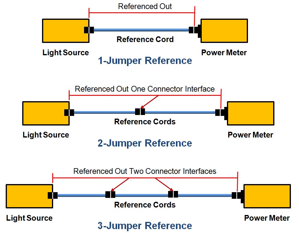
There are several ways to set the reference when using an OLTS, and industry standards specify 1-jumper, 2-jumper and 3-jumper reference methods. The recommended 1-jumper method offers the best accuracy. Let's see why.
As shown in Figure 1, a 1-jumper reference references out the launch cord from the point where it connects to the light source to the point where it connects to the power meter. If you were to use a 2-jumper reference, the mated connection between the two jumpers would also be referenced out. And a 3-jumper reference would add yet another mated connection that was referenced out.
So how does that translate to testing? Depending on which method you choose, the loss associated with the connections at the ends of the fiber under test will be either included or excluded in the final loss measurement.
When using a 2-jumper method that references out one connection, the final measurement will include only one end connection. As a result, the 2-jumper reference provides only a partial depiction of the total loss. And since all connections play an important part in overall channel loss, the 2-jumper reference method is not recommended; it provides the highest uncertainty of all the methods. The 3-jumper method references out two connectors and therefore excludes the loss of both end connections to the cabling under test.
The 1-jumper method is the only method that includes the loss of the connections at both ends, actually simulating the way the cable plant will be used and providing the lowest uncertainty of all measurement methods. However, it's important to remember that after the reference is set with the single launch cord, the tail cord should still be measured for proper loss -- a maximum of 0.1dB for multimode and 0.2dB for singlemode. And do not remove the launch reference cord once the reference is set or you'll have to start over and set it again.
Exceptions to every rule
The 1-jumper reference assumes that the connector on the power meter is compatible with the cabling under test, which is supported by testers with interchangeable adapters. While rare, there are some instances where one might chose the 2-jumper or 3-jumper methods. The 2-jumper method can be used when there are plugs on both ends of the cabling, or a plug on one cable end and an adapter on the other.
The 3-jumper method can be used when better methods are not practical, such as when the fiber connector of the test reference cord does not match the fiber type of a link or when the connectors on each end of the cabling are different from each other.
For example, the 3-jumper reference cord is used for testing MPO links with an LC tester interface using MPO to LC fanout cords, or when pigtails are spliced onto both cable ends and directly connected into transmission equipment.
Regardless of the exceptions, whenever possible use the 1-jumper reference method when testing fiber link loss--it's what the pros use.